Comments (0) likes (0) upload a. 500w power amplifier 2sc2922, 2sa1216 with pcb layout design this is high power amplifier has output power about 500 watt with the compatible voltage supply.
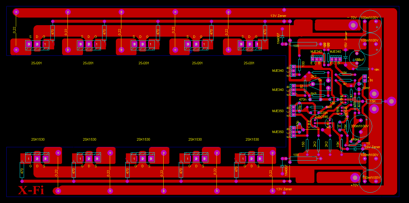
500W amplifier driver layout SHEMS

The tl494 ic has 8 functional blocks which are shown and described below.

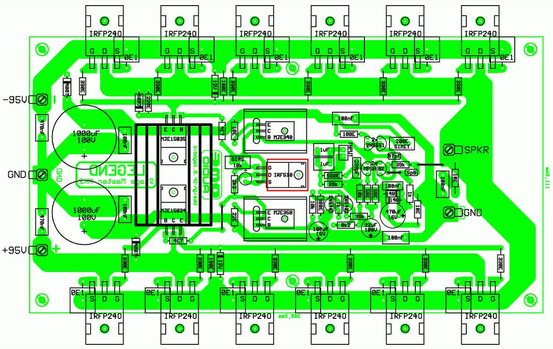
500w amplifier pcb. Ad over 70% new & buy it now; This is the pcb design and component placement, you should mount the mosfet on the heatsink to prevent overheating and maintain the performance of power amplifier. The board is 4x6 and has 2 oz.
Tl494 class d amplifier smps 390w 32v. In addition to all the details, calculation, circuit diagram and pcb drawings given in the gerber files, there is. Electronics projects, rms 500w amplifier circuit audio amplifier circuits, transistor amplifier, date 2019/08/01.
Open areas 500w and 250w hifi amplifier for voice friends circuit is a circuit circulating in the market that only i did some changes on the circuit. At these powers your better off buying a commercial pa amplifier. 500w power amplifier 2sc2922, 2sa1216 with pcb layout design this is high power amplifier has output power about 500 watt with the compatible voltage supply.
Recommend airlink cm0750255 toriodal or similar. High power amplifiers are only for the experienced as they involve dangerous voltages. 500w rms power amplifier pcb design and layout.
This pallet can drive amplifiers with 1 or 2 blf861a's and all of the new 500w pallets that use the new ldmos high voltage devices. 300 500w subwoofer power amplifier transistor circuit rms based mosfet 400w stereo pcb layout super ocl 500 watt n channel circuits 2000 watts ultra 50 audio 1000 with q simple high diagram 200w 300w mini headphone guitar 250 dj inverter using 100 sub woofer working electronic diy 108. 250w 500w hifi amplifier circuits electronics projects.
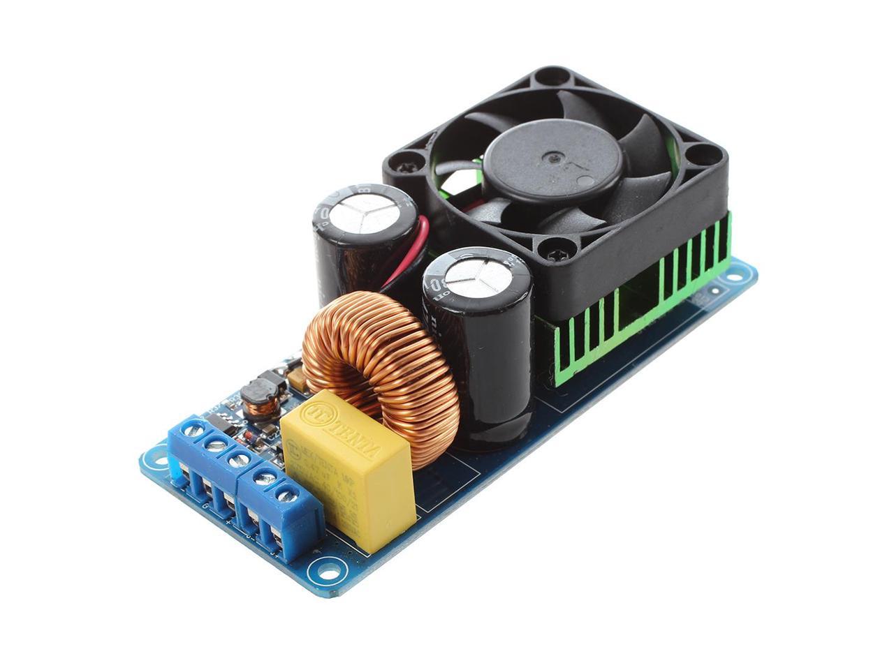
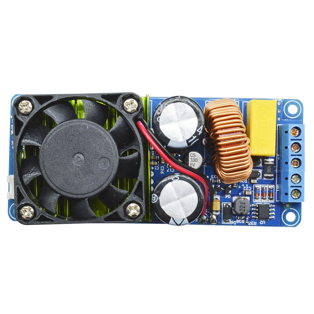
Tl494 class d amplifier circuit 500w amplifier solderingmind com. Electronic life hacks power supply 500w circuit for amplifier jlcpcb prototype for $2(any color): 500w class ab amplifier with integrated source.
400 watts stereo audio amplifier board diy 2sc5200+2sa1943. The output of the amplifier transistors used in german dynacord company that uses transistors and +200 degree weather even has the ability to work. This is the new ebay.
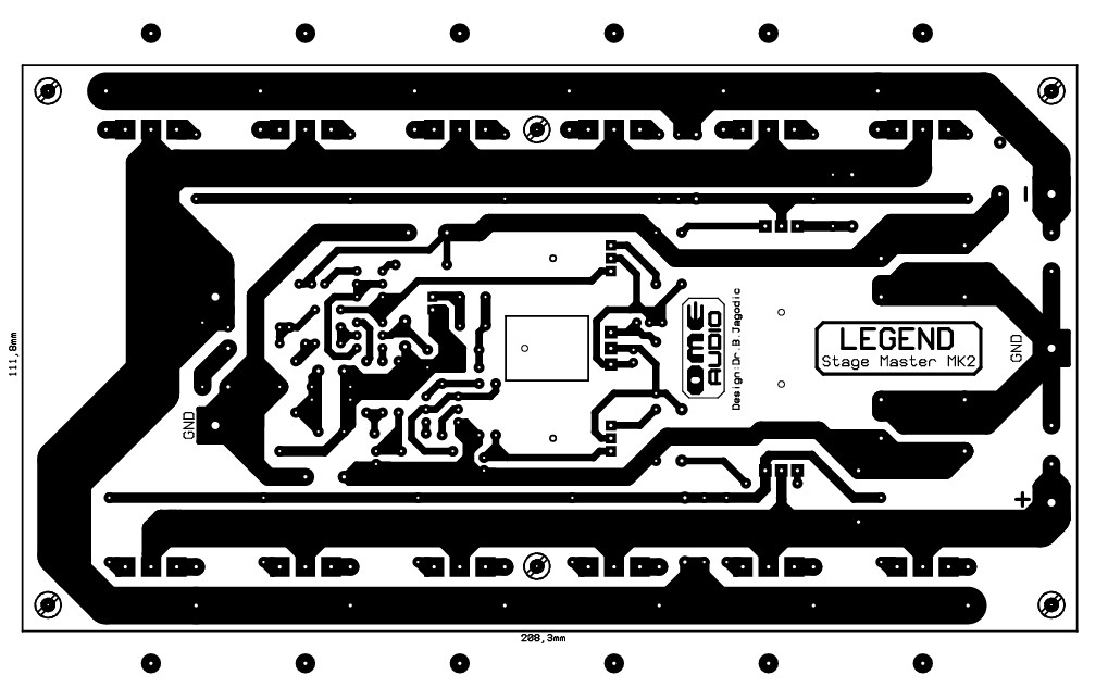
This circuit designed by dr borivoje jagodic >> original page for the reference. Using a pair of vrf2933's it will make 500w output with 5w drive or with a pair of vrf2944's it will make 700w with 7w drive. I decided to design this amplifier since this circuit has great audio quality and impressive stability which makes this circuit perfect to work in concerts or professional sounds, this card was designed because i have observed that in concerts and events the amplifiers, this because they work at.
500w power amplifier 2sc2922, 2sa1216 with pcb layout design this is high power amplifier has output power about 500 watt with the compatible voltage supply. Find 500w amplifier pcb now! 500w class d switching circuit international rectifier irs2092 in the pdf file prepared for the integration of the output coil cooler and so on.
Have a good day guys, introduce us, we from carmotorwiring.com, we here want to help you find wiring diagrams a re you looking for, on this occasion we would like to convey the wiring diagram about 500w audio amplifier circuit diagram pcb. Pcb now available f rom far circuits (see below) Irs2092 class d power amplifier reference design 25w 500w schematic circuit diagram.
Also the parts you need will cost about as much if not more than a off the shelf amp. 100 watt sub woofer amplifier working and circuit diagram. The rf power tools amplifier deck is based on microsemi's an1819 application note.
This pallet can be driven directly by any standard tv modulator making it the only driver you will ever need guaranteed! The hf project was eventually scrapped because of widely varying gain from 160m to 10m. 50mhz 500w irf510 based amplifier.
System 500w rms at 4 ohm 620w rms power gives 2ω, 4ω 500w rms, 8ω 380w rms circuit of the original scheme 8 mosfets used and 4ω 400w writes 2ω speakers in order to work 10 mosfet i used the original transistors toshiba. So the efficiency of the circuit becomes 716958 829539 x 100 8642. Circuit so super now and is working smoothly.
2x500w Power Amplifier assembly NomadTronics

RMS 500W Amplifier Circuit Electronics Projects Circuits

Power Amplifier Super OCL 500W Circuit Electronic Circuit

500w Amplifier 20 Pcb Free YouTube
Apex Amplifier Circuit Diagram / Fet400 Mosfet Amplifier

300W500W After Stage Amplifier Circuit PCB Board Amp base
EBB 500 Mosfet Amplifier Module 500W RMS Audio Disco PA

IRS2092S 500W Mono Channel Digital Amplifier Class D HIFI

500w Mono Amplifier PCB Price Details Amplifier Boards
500W RMS Power Amplifier Based MOSFET Electronic

500W Power Amplifier 2SC2922, 2SA1216 with PCB Layout

500W Stereo Amplifier PCB

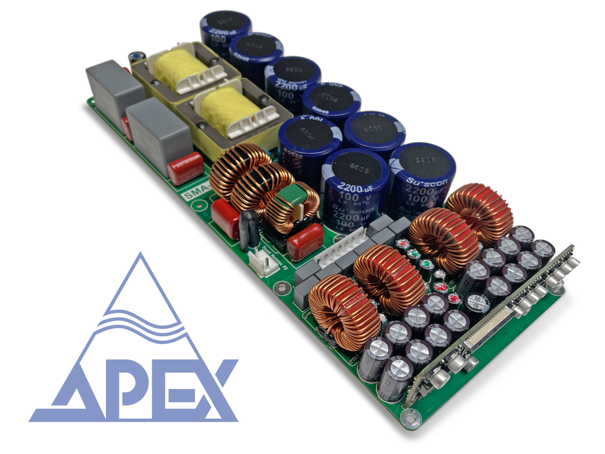
500W Power Amplifier Circuit Apex B500 apex b500 power

500W Power Amplifier 2SC2922, 2SA1216 with PCB Layout

500W Power Amplifier 2SC2922, 2SA1216 with PCB Layout
IRS2092S 500W Mono Channel Digital Amplifier Class D HIFI

AMP Board,Digital Power Circuit Board Audio
500W Power Amplifier 2SC2922, 2SA1216 with PCB Layout
500W RMS Power Amplifier Based MOSFET Circuit Scheme